The assembly of injection molds is an extremely critical process in injection production, which directly affects the stability of mold operation, the quality of injection molded products, and production efficiency. Good assembly not only requires the precision of the coordination between various components to meet the design requirements, but also requires the reasonable arrangement of guidance, cooling, exhaust, and injection systems to ensure smooth coordination of mold closure, molding, opening, and ejection actions.
1、 Identification and preparation: Mold structural components and standard components
1. Mold plates and standard parts
Mold Base: The skeleton that supports all mold parts and needs to be checked for flatness and parallelism to ensure no warping.
Guide Pillars&Bushings: Ensure precise alignment between the moving and fixed molds, with a fit clearance within the range of 0.01-0.03mm; During assembly, insert the guide post first and then insert the guide sleeve to ensure smooth sliding and no shaking.
Ejector Pins&Springs: The core of the ejector mechanism requires verification of the ejector pin length and spring travel to avoid jamming or insufficient travel during ejection.
2. Core and cavity components
Slides and Lifters: Used when lateral core pulling is required. Before installation, it is necessary to confirm that the angle of the inclined guide column and the reset mechanism are unobstructed.
Cooling Manifold: Ensure that the corresponding cooling channels and quick couplings are intact and leak free, assemble and conduct pressure tests first.
2、 Assembly sequence and techniques
1. Template setting first
Place the template flat on the workbench and check its flatness.
Install the positioning column, guide sleeve, and cooling plate, and first perform a sealing test with low-pressure air or hydraulic pressure.
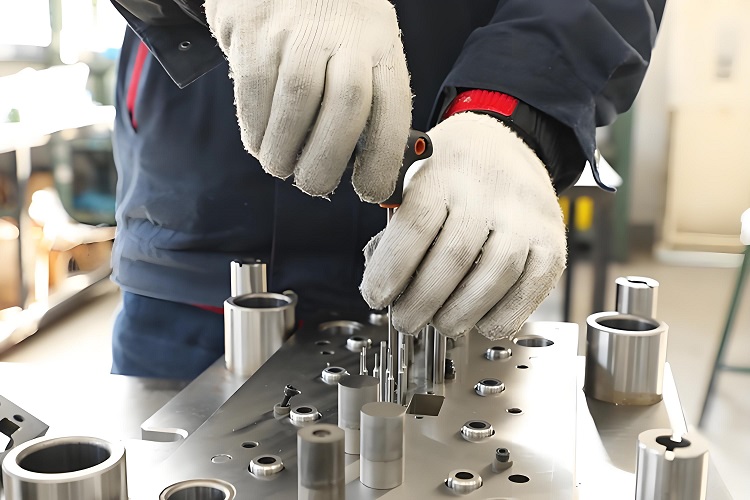
2. Core components are in place
Install the Core component into the template and adjust the positioning pin to ensure it is in place.
Pre install the ejector mechanism, check the travel of the ejector pin, and apply a thin layer of lubricating grease on the ejector pin seat to ensure smooth sliding.
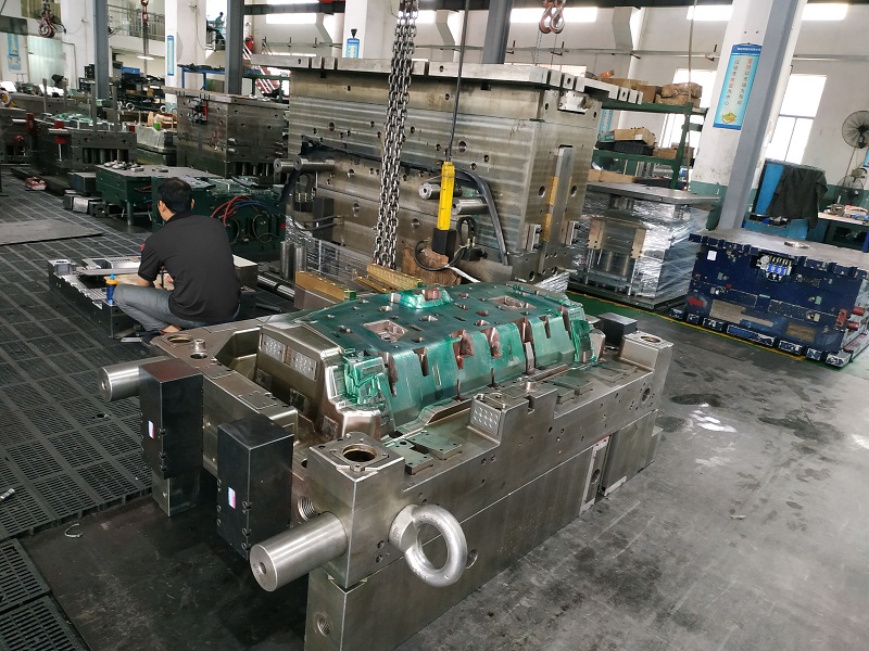
3. Dynamic template alignment
Close the fixed template as a whole with the movable plate and align it with the guide pillars on both sides.
Gradually close the mold and use a feeler gauge to check whether the gap between the parting surfaces is uniform (recommended to be within the range of 5-10 μ m), ensuring that there is no deviation or height after closure.
4. Installation of sliders and inclined tops
Install the slider component on the moving mold side, first install the guide inclined top mechanism, and then tighten the inclined top belt or connecting rod.
After closing the mold, manually push the inclined top rod to confirm that the slider moves smoothly and there is no collision interference.
3、 Alignment and gap adjustment
1. Adjustment of parting surface gap
Uneven clearance between parting surfaces can lead to melt leakage (flash) or local flow resistance. The standard calibration steps are as follows:
After the mold is closed, insert a 0.01 mm feeler gauge at the four corners and center of the mold parting surface, and check the consistency of the gap point by point.
If any deviation is found, adjust the length of the positioning column or add or subtract shims to fine tune the parallelism of the parting surface.
2. Top needle travel setting
The stroke of the ejector pin should be slightly greater than the ejection stroke of the component to avoid insufficient stroke causing inability to eject, or excessive stroke causing the ejector pin to overshoot.
Use stroke limiters or measure the maximum travel of the locking pin with the nut, and test multiple times to confirm.
4、 Installation and verification of auxiliary systems
1. Cooling system
Joint installation: Use quick connectors or card sleeve connectors to connect water pipes. First, use low-pressure water to check for leaks and confirm that there are no leaks before assembly.
Flow rate and temperature difference: It is recommended to control the temperature difference between the inlet and outlet of the cooling circuit at 5-10 ℃, and verify the flow balance of each circuit through a flow meter.
2. Exhaust system
Reserve 0.02-0.05mm exhaust slots at the end of the mold cavity and next to the slider, and conduct an air injection test after assembly to ensure that air can escape smoothly without material leakage.
3. Heating and temperature control
Heating coil arrangement: For areas sensitive to temperature differences or prone to sticking materials, install heating coils and cover them with high-temperature resistant silicone tubing to avoid excessive temperature gradients.
Temperature sensor: Install thermocouples at key positions of the mold (gate, junction, thin-walled area) and conduct simulation control tests after assembly.
5、 Trial molding and calibration
1. First piece trial mold
After assembly, conduct a first piece trial mold and strictly record the molding parameters, ejection stroke, and finished product condition.
Check for defects such as burrs, weld marks, shrinkage, and warping, and adjust the parting surface gap, cooling time, or exhaust position according to the defect location.
2. Fine tuning and mass production debugging
Injection parameter optimization: During the trial molding process, the parameter scanning method (DOE) is used to optimize the injection speed, pressure, and holding pressure curve to ensure stable molding.
Automated monitoring docking: Integrate mold assembly data with the injection molding machine monitoring system to achieve real-time mold temperature and pressure monitoring, improving subsequent switching efficiency.
3. Regular maintenance
After each batch or every 5000 cycles, it is recommended to perform mold calibration and top pin/guide sleeve inspection, replace worn parts in a timely manner, and maintain assembly accuracy and molding consistency.
6、 Common problems and precautions
Assembly environment: The assembly workshop should be kept clean and dust-free, with temperature controlled at 20-25 ℃ and humidity at 40-60% to avoid parts rusting or dimensional drift.
Tightening force: The bolt locking torque must be strictly executed according to the mold specifications to avoid deformation caused by over tightening or loose fitting caused by over loosening.
Recording and Traceability: Each assembly step, adjustment data, and trial mold result should be recorded in detail to facilitate subsequent fault tracing and process reproduction.
Through the system assembly and calibration of the six major links mentioned above, the closing accuracy, exhaust efficiency, cooling uniformity, and smooth ejection of injection molds can be effectively guaranteed, providing a solid foundation for high-quality and stable injection production. Reasonable application of the above assembly techniques can significantly shorten the trial mold cycle, reduce maintenance costs, and extend the service life of the mold.